
Building physical hardware requires turning a digital CAD drawing into a tangible object that fits together, powers on, and withstands actual usage. Without physical testing, small design flaws turn into costly mass production failures.
| Stage | Milestone | Primary Output | Main Risk Mitigated |
| Stage 1 | Idea / Concept | Industrial Sketches & Requirements | Unrealistic Product Scope |
| Stage 2 | CAD & DFM | 3D Models & Circuit Schematics | Tooling Errors & Interference |
| Stage 3 | EVT / DVT / PVT | Validated Hardware Builds | Regulatory & Yield Failures |
| Stage 4 | Mass Production | High-Volume Shipping Units | Scale Bottlenecks |
At Precintl, our engineering team guides hardware startups and established OEMs through every stage of this transformation. This comprehensive guide details the practical mechanics of physical iteration, testing regimes, and scaling strategies.
What Is Prototyping in Product Development?
The product development process relies on physical verification. An early draft hardware model acts as a physical hypothesis, allowing engineers to test mechanics, thermal dynamics, and circuit performance before committing to expensive tooling.
Prototype vs. Proof of Concept vs. Final Product
| Phase | Main Objective | Key Characteristics | Typical Materials |
| Proof of Concept (PoC) | Validate basic feasibility | Rough, functional core, non-integrated | Off-the-shelf development boards, breadboards, raw stock |
| Product Prototype | Refine form, fit, and function | Represents actual geometry and custom electronics | 3D prints, CNC machined stock, rapid PCB prototyping |
| Final Product | Mass production readiness | High volume, fully certified, cosmetically finished | Injection-molded plastics, custom metal stampings, mass PCBs |
A proof of concept prototype answers a simple question: Can this technology work? For instance, an engineer might wire a sensor to an Arduino board to verify signal output.
A hardware prototype answers a complex question: Can we integrate this technology into a marketable enclosure? The final product represents the polished result of that iterative design process, optimized for high-volume manufacturing lines.
Why Prototyping Matters Before Manufacturing
Skipping physical testing invites severe manufacturing risks. Tooling for a plastic enclosure often costs tens of thousands of dollars and takes weeks to build. Cutting steel molds based purely on unverified 3D models risks costly rework if parts warp or clip together incorrectly. Early prototype development catches tolerance issues, thermal hot spots, and assembly bottlenecks while design changes only require updating a CAD file.
What a Good Product Prototype Should Validate
A complete validation process checks three primary criteria:
- Mechanical Fit: Ensuring enclosure halves snap together with correct tolerances and seal against environmental elements.
- Electrical Performance: Verifying that power distribution networks remain stable under peak loads without causing EMI interference.
- User Ergonomics: Testing button actuation force, display clarity, and physical handling in real-world scenarios.
Types of Product Prototypes
Different design phases require different levels of prototype fidelity. Selecting the correct type prevents overspending early in development.
| Prototype Category | Focus Area | Dominant Manufacturing Technology | Primary Stakeholder |
| Concept & Appearance | Visual aesthetics, proportions, textures | SLA 3D Printing, Urethane Casting, Hand Finishes | Industrial Designers, Investors |
| Functional & Engineering | Mechanical strength, electrical circuits | CNC Machining, FDM/SLS Printing, SMT Assembly | Mechanical & Electrical Engineers |
| Production-Ready | Mass-market tooling, supply chain fit | Rapid Injection Molding, Stamped Metals, Multi-layer PCBs | Quality Engineers, Operations |
Concept and Appearance Prototypes
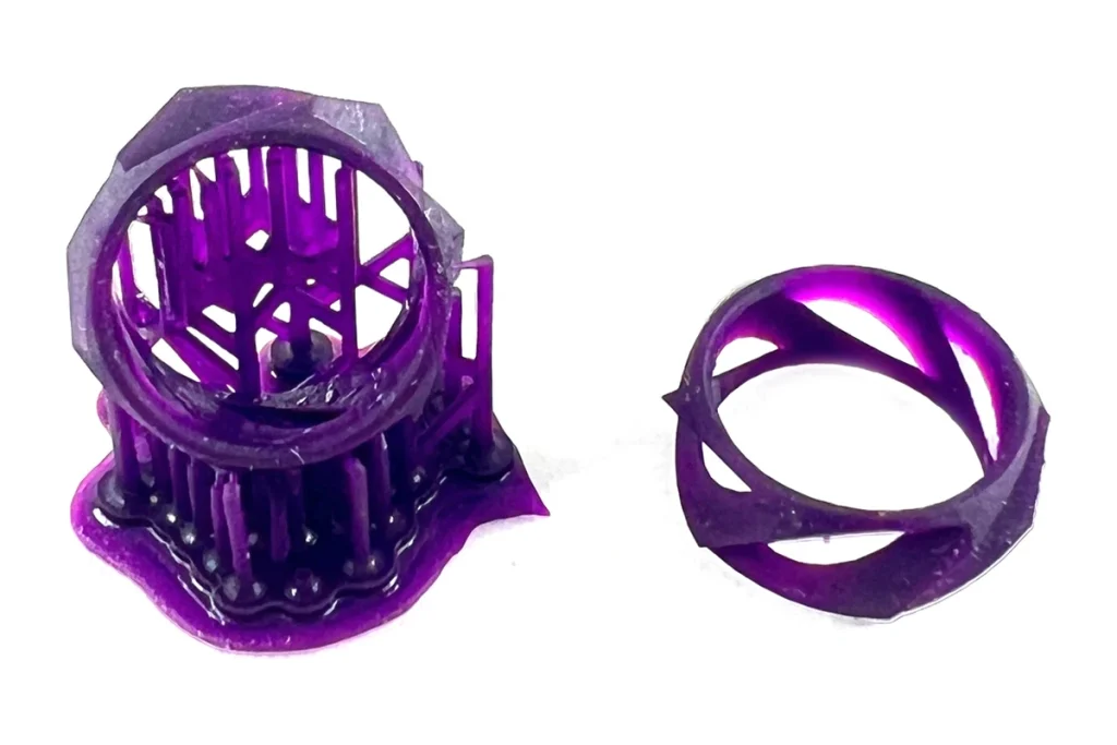
Concept models focus strictly on aesthetics and visual appeal. Designers use industrial product prototyping to evaluate proportions, color palettes, and surface finishes. These units are often solid blocks crafted via SLA 3D printing, finished with custom paint and texture coatings to resemble mass-produced consumer items for trade shows or investor pitches.
Functional Prototypes
A functional prototype prioritizes performance over surface appearance. Engineers use these builds to evaluate internal mechanisms, latches, and structural integrity. A functional prototype often utilizes CNC-machined engineering plastics like ABS or POM to match the mechanical strength of final molded parts.
Engineering Prototypes
An engineering prototype combines functional mechanics with custom circuit designs. These builds feature early custom printed circuit boards (PCBs) placed inside representative enclosures. They allow hardware teams to begin integration testing, firmware flashing, and initial thermal evaluation.
Production-Ready Prototypes
A production-ready prototype matches the final mass-manufactured product as closely as possible. It utilizes components sourced from actual supply chain vendors, final circuit board layouts, and high-precision production processes. Achieving a production-ready prototype signals readiness for formal regulatory compliance testing.
Electronics and Hardware Prototypes
For hardware products, an electronic product prototype requires parallel iteration: custom PCB prototyping alongside custom mechanical enclosure builds. Connecting hardware prototyping directly to early firmware code ensures that sensors, microcontrollers, and wireless modules operate reliably within heat-generating enclosures.
The Product Prototyping Process From Idea to Prototype
Converting an idea into a physical build demands structured execution across multiple engineering fields.
| Step | Workflow Stage | Operational Scope | Key Deliverables |
| 1 | Specifications | Define mechanical, electrical, and environmental targets | PRD & BOM targets |
| 2 | ID & Mechanical | Draft surface aesthetics, internal ribbing, and mountings | 3D CAD Assembly (.STEP) |
| 3 | Electronics & Firmware | Schematic layout, PCB routing, and low-level drivers | Gerber Files & C/C++ Firmware |
| 4 | Virtual Integration | 3D collision check and thermal clearance validation | Integrated CAD Package |
| 5 | Material Selection | Match polymer and alloy stock to mechanical stress | Sourced Bill of Materials |
| 6 | Build & Iterate | Fabricate physical units, flash code, and log defects | Physical Prototype Units |
Defining Product Requirements and Specifications
Successful builds begin with clear engineering inputs:
- Operating temperature range and IP ratings for moisture/dust ingress.
- Target unit cost (BOM target) and expected operational lifespan.
- Power budgets, battery capacities, and wireless protocols (BLE, Wi-Fi, Cellular).
- Mechanical dimensions, weight limits, and drop-test requirements.
Industrial Design and Mechanical Engineering
Industrial designers draft initial form factors using ergonomics and brand guidelines. Mechanical engineers then translate these surface models into fully functional CAD files, designing internal ribbing, screw bosses, snap fits, and thermal heat sinks.
Electronics, PCB, and Firmware Development
Electrical engineers select microcontrollers, power management ICs, and passive components based on defined feature specifications. They design circuit schematics and lay out multi-layer PCBs while firmware engineers write driver code, power-saving logic, and RF stack initializations for IoT prototyping.
Related: EMS Electronic Manufacturing Explained: From Design to Mass Production (2026)
CAD Design and Prototype Engineering
During prototype engineering, mechanical and electrical CAD data merge. Engineers perform spatial checks to verify component heights, connector alignments, and cable routing within the housing before ordering physical parts.
| Enclosure Layer | Component Focus | Key Engineering Check |
| Upper Shell | User Interface, Buttons, Status LEDs | Wall thickness consistency and display window clarity |
| Internal PCBA | Microcontroller, Power IC, Wireless Module | Clearances around tall capacitors and thermal pads |
| Lower Shell | Battery Compartment, Charging Port, Screws | Snap-fit engagement depth and screw boss strength |
Selecting Materials and Components
Choosing appropriate prototype materials ensures accurate testing results. Standard prototyping polymers include ABS, Polycarbonate, Nylon, and PMMA. When testing high-stress parts, aluminum alloys like 6061-T6 or stainless steel offer real-world durability.
Building and Iterating the Prototype
With files finalized, custom prototype manufacturing begins. Engineers assemble the physical units, flash firmware, run functional passes, and record failures. Each prototype iteration resolves identified bugs before moving to the next validation milestone.
Rapid Prototyping Methods and Technologies
Modern fabrication tools allow teams to turn CAD files into physical parts within days. Selecting the optimal method depends on budget, material needs, and required surface finishes.
| Technology | Ideal Use Case | Pros | Cons |
| 3D Printing | Early visual checks & complex shapes | Zero tooling cost, fast turn | Anisotropic strength in FDM |
| CNC Machining | Load-bearing functional validation | Actual engineering alloys/plastics | Higher unit cost for high quantities |
| Prototype Molding | Low-volume pre-production (50-1000) | Authentic molded plastic properties | Soft aluminum tool lead time |
| Sheet Metal | Heavy industrial enclosures & frames | High durability and structural rigidity | Geometric bending limitations |
3D Printing for Product Prototypes
Additive manufacturing enables rapid geometric verification without upfront tooling fees:
- FDM (Fused Deposition Modeling): Best for early, low-cost dimensional checks using basic thermoplastics like PLA or ABS.
- SLA (Stereolithography): Offers ultra-high resolution and smooth surface finishes suitable for concept appearance models.
- SLS (Selective Laser Sintering): Creates strong, functional nylon parts with complex geometries that require no support structures.
CNC Machining for Functional Prototypes
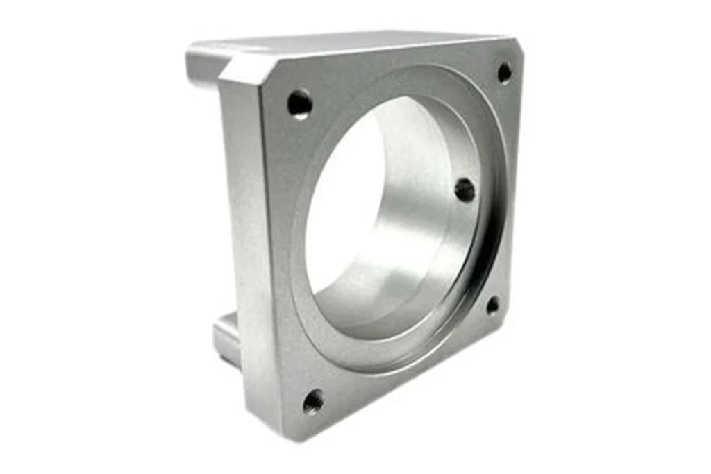
CNC prototyping uses subtractive manufacturing to cut solid blocks of metal or plastic into final parts. This approach offers strict mechanical tolerances (up to ± 0.02 mm), structural strength, and authentic material properties ideal for load-bearing components and thermal heatsinks.
Prototype Injection Molding
When testing requires production-grade plastic parts in higher quantities (50 to 1,000 units), prototype tooling made from soft aluminum offers a middle ground. It delivers real molded parts for testing without the high costs of hardened steel mass-production molds.
Sheet Metal and Fabrication Prototyping
Sheet metal prototype fabrication uses laser cutting, CNC bending, and welding to create robust enclosures for industrial hardware, rack-mounted equipment, and power supplies.
Choosing the Right Prototyping Method
| Fabrication Method | Production Lead Time | Material Options | Dimensional Accuracy | Cost per Unit (Low Vol) |
| 3D Printing (SLA/SLS) | 1 – 3 Days | Resin, Nylon | Medium (± 0.1 mm) | Low |
| CNC Machining | 3 – 7 Days | ABS, PC, Aluminum, Steel | High (± 0.02 mm) | Medium – High |
| Sheet Metal | 3 – 5 Days | Steel, Aluminum, Brass | Medium (± 0.1 mm) | Medium |
| Rapid Injection Molding | 2 – 4 Weeks | ABS, PC, PP, TPE | High (± 0.05 mm) | High Initial Tooling |
Electronics and IoT Product Prototyping
Smart device prototyping requires deep coordination between electronic, mechanical, and software disciplines.
| IoT Integration Stage | Action Item | Primary Test Benchmark |
| Stage 1: Board Bring-Up | Supply power to custom PCBA | Measure voltage rails and clock signals |
| Stage 2: Firmware Flash | Load bootloader & baseline drivers | Verify sensor readings via serial debug |
| Stage 3: RF Optimization | Tune antenna matching circuit | Check RSSI values and packet drop rates |
| Stage 4: System Integration | Assemble PCBA inside enclosure | Monitor thermal rise during active transmission |
PCB Prototype Development
Printed circuit board builds follow a strict path:
- Schematic Capture: Define electrical nets, components, and pinouts.
- PCB Layout: Place components and route traces across 2 to 8 circuit layers.
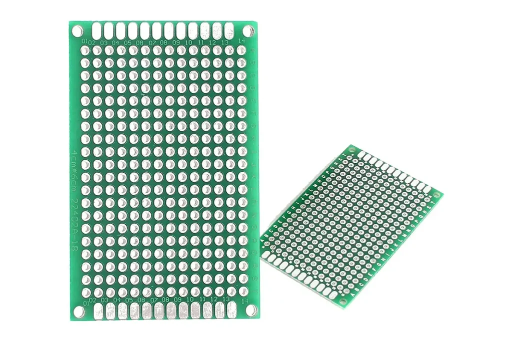
- Bare Board Fabrication: Etch copper layers, drill vias, and apply solder mask.
- SMT Assembly: Place surface-mount components via pick-and-place systems and reflow solder them.
Hardware and Component Integration
Once the circuit board arrives from assembly, technicians install connectors, displays, batteries, and mechanical switches. Fastening wire harnesses and verifying power rails prevents voltage spikes from damaging sensitive components.
Connectivity and Firmware Validation
Smart connected hardware requires RF validation. Engineers flash baseline firmware to test Bluetooth, Wi-Fi, or cellular connections, analyzing antenna gain, signal strength, and power draw across different transmit states.
| Validation Check | Test Environment | Target Operational Criteria |
| RF Antenna Match | Anechoic Chamber / RF Bench | Low reflection loss, stable RSSI across target band |
| Power Consumption | Current Profiler | Low sleep current (< 20 µA), controlled peak active spikes |
| Thermal Profiling | Thermal Camera Chamber | Continuous load temperature under critical junction limits |
Enclosure and Mechanical Integration
Fitting an active circuit board into an enclosure highlights hidden mechanical conflicts. Antenna placement must maintain clear line-of-sight away from metallic internal structures or shielding cans that block wireless signals.
Testing Smart and Connected Devices
IoT product validation involves testing connectivity under varied battery levels and signal environments. Environmental test chambers evaluate wireless performance from -20°C up to +60°C.
Related: How Does Contract Manufacturing Work? Process, Costs & Benefits
How Design for Manufacturing Improves Prototypes
Design for Manufacturing (DFM) bridges early CAD concepts and mass-market production lines. Integrating DFM prototyping rules early prevents major redesigns late in the development cycle.
| DFM Core Area | Common Design Flaw | Manufacturing Remedy |
| Injection Molding | Non-uniform wall thickness | Add internal core-outs and maintain uniform thickness |
| CNC Machining | Deep, sharp internal corners | Radius all internal corners to match standard end-mill tools |
| Sheet Metal | Bend relief areas placed too close to holes | Maintain distance equal to 2x sheet thickness from bends |
DFM Checks Before Prototype Production
Before sending CAD files to production, engineers verify several core molding and machining rules:
- Uniform Wall Thickness: Prevents sink marks and material warping in plastic injection parts.
- Draft Angles: Ensures plastic parts eject cleanly from mold cavities without dragging.
- Undercut Minimization: Reduces the need for complex side-actions in tooling, lowering costs.
Material and Component Availability
Designing custom hardware with obscure, single-source electronic components introduces supply chain vulnerabilities. Experienced design teams prioritize active, multi-sourced components readily available through distribution networks like Arrow, DigiKey, or Mouser.
Manufacturing Tolerances and Specifications
Over-specifying tight tolerances across an entire design inflates custom prototype manufacturing cost without adding functional value. Engineers focus strict tolerances (± 0.01 mm) on critical mating features, leaving secondary external surfaces at standard commercial tolerances (± 0.1 mm).
Reducing Prototype-to-Production Changes
Applying DFM standards early keeps your design stable. When your functional prototype uses the same wall thicknesses, ribbing, and component layouts planned for mass production, scaling up becomes a smooth transfer rather than a total redesign.
Prototype Testing and Product Validation
Systematic testing identifies design bugs early, ensuring safety, reliability, and functional compliance before commercial launch.
| Validation Category | Test Method | Primary Objective |
| Functional & Performance | Automated electrical test benches | Confirm features match target technical specs |
| Design & Ergonomics | User handling surveys & focus testing | Evaluate button feedback, grip, and visual layout |
| Reliability & Stress | Drop towers, environmental chambers | Force hardware failures under extreme stress |
| Regulatory Compliance | Pre-compliance chamber testing | Ensure compliance for FCC, CE, RoHS, and UN38.3 |
Functional and Performance Testing
Functional verification confirms the unit executes its core features under normal operating conditions. Engineers test voltage stability, button responsiveness, sensor sampling rates, and motor control loops.
Design Validation
Design validation checks whether the product meets user needs and market requirements. This process confirms that industrial design choices—such as weight distribution, grip texture, and visual indicator LED brightness—align with product goals.
Reliability and Durability Testing
Hardware must survive real-world wear and tear. Reliability testing subjects units to demanding physical stress:
- Environmental Stress: Thermal cycling inside temperature/humidity chambers.
- Mechanical Shock: Automated drop testing onto concrete surfaces from heights of 1.2 meters.
- Ingress Protection: Testing water spray and dust resistance to verify IP ratings.
Usability and Real-World Testing
Deploying functional prototypes to real field testers highlights unpredicted user behaviors. User feedback reveals software edge cases, awkward handling angles, or ambiguous status LED behaviors.
Identifying and Resolving Prototype Failures
When a prototype fails a stress test, engineers conduct root-cause analysis (RCA). If a plastic clip snaps during a drop test, mechanical teams perform finite element analysis (FEA) to reinforce stress zones before launching the next iteration.
From Prototype to Mass Production
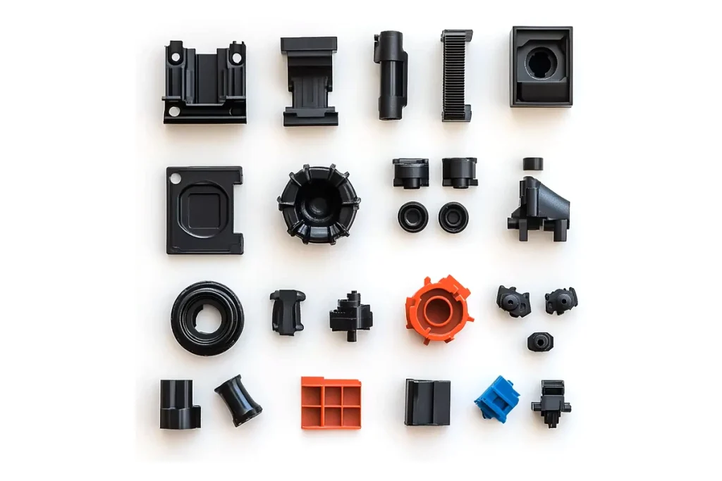
| Validation Phase | Primary Objective | Typical Build Quantity | Key Acceptance Criteria |
| EVT (Engineering Validation) | Prove core functional mechanics & PCBA | 20 – 50 Units | 100% functional feature pass rate |
| DVT (Design Validation) | Validate cosmetics, drop strength, certification | 50 – 200 Units | Pass FCC/CE/RoHS & environmental tests |
| PVT (Production Validation) | Test assembly line speed, yields & QC fixtures | 100 – 500 Units | Line yield rate exceeds target (> 98%) |
Engineering Validation Testing (EVT)
EVT focuses on validating core engineering functionality. Units are built using prototype manufacturing processes (like CNC or 3D printing) and early custom PCBs to confirm thermal, electrical, and mechanical performance.
Design Validation Testing (DVT)
DVT confirms the product meets cosmetic, mechanical, and regulatory standards using final production processes. Units are built using production-grade injection tooling and SMT lines to undergo formal FCC, CE, and RoHS certifications.
Production Validation Testing (PVT)
PVT tests the mass manufacturing assembly line itself. Built at target production speeds on factory floors, these units verify assembly line tools, worker instructions, quality control yields, and throughput times.
Pilot Production and Manufacturing Validation
Pilot production runs (typically 100 to 500 units) validate factory yield rates. Quality engineers track defect rates at each assembly station to refine yield figures before full factory authorization.
Transitioning a Production-Ready Design to Mass Production
Once PVT yield rates exceed target benchmarks (typically > 98%), the production-ready design transfers to full mass manufacturing. The custom tooling, tested SMT assembly scripts, and verified quality control fixtures lock into place for high-volume execution.
Related: OEM vs ODM Manufacturing: Which Is Right for Your Product?
Prototype Manufacturing Costs and Lead Times
| Prototype Fabrication Approach | Typical Lead Time | Expected Cost Range | Best Suited Project Stage |
| 3D Printed Visual Mockup | 2 – 4 Business Days | $200 – $1,000 | Early Concept & Form Factor Review |
| Complex IoT PCB + CNC Housing | 2 – 3 Weeks | $3,000 – $12,000 | Functional & Engineering Validation |
| Rapid Injection Molded Soft Tooling | 3 – 5 Weeks | $8,000 – $25,000+ | Pre-Production DVT & Field Pilot Runs |
What Determines Prototype Cost?
Main cost factors include:
- Raw Material Grade: High-performance plastics (PEEK, PTFE) and specialized metal alloys cost significantly more than standard ABS or Aluminum 6061.
- Manufacturing Technique: Multi-axis CNC machining incurs higher hourly machine rates than basic SLA 3D printing.
- Secondary Finishing: Hand polishing, clear coating, anodizing, and custom silk-screening add manual labor time.
Prototype Quantity and Material Selection
Building 1 to 5 units favors additive manufacturing or CNC machining due to zero setup tooling costs. Producing 100 to 1,000 units makes rapid injection molding or low volume manufacturing far more cost-effective per unit.
Tooling and Engineering Costs
Initial setup costs cover non-recurring engineering (NRE), PCB assembly stencils, custom CNC fixtures, and soft injection molds. While NRE increases early costs, it reduces per-unit costs during volume scaling.
How Prototype Complexity Affects Lead Time
Simple mechanical 3D prints take 2 to 4 days. Complex IoT products requiring custom multi-layer PCB assembly, overseas component sourcing, and CNC-machined enclosures typically require 2 to 4 weeks.
How to Choose a Prototype Manufacturing Partner
| Partner Evaluation Criteria | Key Verification Questions | Risk of Choosing Wrong Partner |
| In-House Engineering | Do they perform full DFM reviews before machining? | Parts arrive unmanufacturable or warped |
| Supply Chain Network | Do they source components directly from franchised distributors? | Fake or obsolete components cause PCB failures |
| Quality Control Systems | Are they ISO 9001 and ISO 13485 certified with CMM gear? | Out-of-tolerance parts delay assembly |
| Scaling Capabilities | Can they transition the build directly into injection tooling? | Costly design rework when switching suppliers |
In-House Engineering and Design Capabilities
A capable partner provides dedicated mechanical, electrical, and firmware engineering support. In-house engineering teams identify design flaws and run DFM checks before committing to hardware fabrication.
Manufacturing and Supplier Network
A broad vendor network ensures quick component sourcing, stable supply chains, and competitive material pricing during both prototype fabrication and volume production phases.
Quality Control and Testing Processes
Evaluate your vendor’s quality assurance standards. Verify they use high-precision Coordinate Measuring Machines (CMM), optical measuring systems, and automated X-ray inspection (AXI) for circuit assemblies.
Prototype-to-Production Capabilities
Working with a single team for both prototyping and mass production eliminates friction when transferring assembly instructions, testing fixtures, and tooling configurations.
OEM and ODM Manufacturing Experience
An experienced OEM/ODM provider understands how to navigate supply chain risks, streamline regulatory certifications, and scale production efficiently.
Common Prototyping Mistakes Businesses Should Avoid
| Common Development Mistake | Direct Impact | Strategic Prevention Strategy |
| No Clear PRD | Scope creep and budget overruns | Lock technical specs before releasing initial CAD |
| Ignoring DFM Standards | Tooling redesigns and delayed launches | Conduct DFM checks during the initial modeling phase |
| Wrong Fabrication Choice | False testing results and broken prototypes | Match prototyping method to testing objectives |
| Skipping Reliability Tests | High product return rates after release | Enforce rigorous drop, thermal, and ingress testing |
Prototyping Without Clear Product Requirements
Skipping formal Product Requirement Documents (PRDs) leads to scope creep. Changing battery specifications or wireless range targets midway through PCB prototyping invalidates existing layouts, wasting time and capital.
Ignoring Design for Manufacturing
Designing a complex enclosure in CAD without considering mold draft angles or tool paths creates parts that cannot be molded or machined economically at scale.
Using the Wrong Prototype Technology
Relying on low-cost FDM 3D prints to validate high-stress snap fits or fluid seals yields inaccurate results. Match your fabrication method to your specific validation goals.
Skipping Functional and Reliability Testing
Launching directly into volume production after basic appearance checks risks field failures. Uncut heat dissipation paths or fragile solder joints can destroy brand reputation upon market release.
Failing to Plan for Mass Production
Treating prototype builds as isolated tasks rather than stepping stones toward mass production leads to unexpected scaling costs. Always design with final volume production lines in mind.
Prototyping for Different Product Categories
| Hardware Product Category | Primary Engineering Focus | Critical Regulatory / Material Requirement |
| Consumer Electronics | Sleek cosmetics, tight gaps, drop protection | FCC, CE, RoHS compliance |
| Smart Home & IoT | Wireless performance, ultra-low power modes | Antenna tuning & RF pre-compliance |
| Wearable Devices | Miniature PCB assembly, battery optimization | ISO 10993 skin biocompatibility & IP68 water sealing |
| Pet Technology | Impact resistance, chew-proof housings | Non-toxic materials & ruggedized seals |
| Industrial Hardware | Cast metal housings, vibration resistance | Extended operating temp range (-40°C to +85°C) |
Consumer Electronics
Consumer hardware demands refined aesthetics, tight seam tolerances, sleek surface finishes, and slim profiles while maintaining structural drop-resistance.
Smart Home and IoT Products
Smart devices require clear wireless performance through plastic enclosures, robust power management for long battery life, and simple user setup experiences.
Wearable Devices
Wearables demand ultra-compact multi-layer PCB layout strategies, bio-compatible materials (ISO 10993), low power consumption, and reliable IP67/IP68 water sealing.
Pet Technology Products
Pet hardware requires durable, non-toxic materials, shock-resistant housings, secure battery enclosures, and robust water sealing to withstand rugged daily use.
Industrial and Connected Hardware
Industrial hardware prioritizes high durability over sleek optics. Housings use thick aluminum castings or heavy sheet metal designed for extreme operating temperatures and high vibration environments.
Custom Electronic and Mechanical Products
Unique commercial products demand custom mechanical linkages, specialized sensor integration, and tailored firmware stacks built for dedicated market applications.
How Precintl Supports Product Prototyping and Manufacturing
| Precintl Support Module | Scope of Work | Client Value Delivered |
| Concept & CAD Engineering | Industrial design, mechanical CAD, PCB schematics | Turn abstract ideas into manufacturable CAD files |
| Rapid Prototype Production | 3D printing, CNC machining, rapid SMT assembly | Fast physical parts for early validation |
| EVT / DVT / PVT Execution | Thermal, drop, environmental & RF testing | Risk-free transition into regulatory compliance |
| Mass Factory Scaling | Injection mold tooling, automated SMT, pilot runs | Smooth transition into mass production |
Product Concept, Design, and Engineering
Our engineering team works alongside your team to translate raw product visions into actionable engineering requirements, CAD architectures, and circuit schematics.
Prototype Development and Iteration
Precintl operates rapid prototyping facilities handling 3D printing, high-precision CNC machining, rapid PCB prototyping, and custom sheet metal fabrication to deliver rapid physical iterations.
EVT, DVT, and PVT Validation
We guide your design through EVT, DVT, and PVT phases, running thermal, electrical, drop, and environmental tests to secure full regulatory compliance (FCC, CE, UL).
Supply Chain and Component Sourcing
Our global supply chain network secures authentic electronic components, manages material lead times, and stabilizes unit costs against market volatility.
Pilot Production to Mass Manufacturing
Precintl bridges low-volume prototype builds with full-scale automated factory lines, ensuring high manufacturing yields and reliable quality control.
OEM and ODM Product Development Under One Partner
By combining complete OEM prototyping services and ODM product development under one roof, Precintl reduces product launch risks and accelerates your time-to-market.
Technical Appendix: Practical DFM Checklist for Physical Prototype Builds
To further support hardware engineering teams, product managers, and startups transitioning from initial CAD designs to mass-produced physical hardware, Precintl has compiled this operational checklist. Incorporating these rules directly into your prototype manufacturing process reduces design revisions and prevents costly tooling rework.
| Engineering Parameter | Recommended Specification Target | Common Tooling Failure Prevented |
| Plastic Wall Thickness Consistency | Maintain within ± 10% variation | Prevent surface sink marks and wall warping |
| Injection Mold Draft Angles | 1.0° to 2.0° nominal draft angle | Avoid wall drag marks during part ejection |
| Internal CNC Pocket Radius | Radius ≥ 0.5 x Pocket Depth | Prevent tool chatter and excessive tool wear |
| SMT Component Edge Spacing | Minimum 0.25 mm clear clearance | Prevent solder bridging and pick-and-place errors |
| Screw Boss Engagement Depth | 1.5x to 2.0x thread diameter | Eliminate boss cracking under torque stress |
Partner with Precintl for Full-Lifecycle Hardware Execution
From early conceptual drafting and rapid prototyping services to complete prototype to mass production scaling, Precintl provides end-to-end engineering, manufacturing, and supply chain management.
- Direct Engineering Support: Work directly with experienced mechanical, electrical, and firmware engineers.
- Global Supply Chain Management: Access stable component pipelines to prevent supply chain bottlenecks.
- Turnkey Manufacturing Facilities: Scale seamlessly through EVT, DVT, and PVT stages into full commercial production under one single partner.
Ready to launch your product? Send your CAD models and project specifications to the engineering team at Precintl to receive a comprehensive DFM evaluation and manufacturing quote.
Frequently Asked Questions About Prototyping
What is prototyping in product development?
Prototyping is the physical creation and testing of preliminary hardware models to validate design feasibility, mechanical fit, electronic operation, and user experience before launching volume manufacturing.
How much does product prototyping cost?
Costs vary based on complexity. Simple 3D-printed visual models run from $200 to $1,000. Complex electronic product prototypes requiring multi-layer PCBs, custom CNC enclosures, and DFM validation generally cost between $5,000 and $30,000+.
How long does it take to make a prototype?
Basic visual models take 2 to 5 days. Full functional prototypes featuring custom electronics, programming, and CNC-machined enclosures typically require 3 to 6 weeks.
What is the difference between rapid prototyping and traditional prototyping?
Rapid prototyping uses additive manufacturing (3D printing) and high-speed automated CNC machines to deliver parts in days without custom tooling. Traditional prototyping relies on manual machining, soft tooling, or custom master patterns, which takes longer but delivers production-grade material properties.
Which prototyping method is best for a new product?
It depends on your current stage. Early visual checks benefit from SLA 3D printing. Functional mechanical testing requires CNC machining, while pre-production volume runs require prototype injection molding.
Can a prototype be manufactured at scale?
Prototypes are crafted for validation, not mass output. However, applying Design for Manufacturing (DFM) rules during early prototyping ensures your design can seamlessly transition into volume production.
What are EVT, DVT, and PVT in product development?
These three phases validate production readiness:
- EVT (Engineering Validation Testing): Tests core functional features.
- DVT (Design Validation Testing): Tests physical durability, aesthetics, and regulatory standards.
- PVT (Production Validation Testing): Tests factory assembly speed and line yields.
How do I move from a prototype to mass production?
Transitioning requires finalizing CAD/DFM files, building production tooling, setting up factory assembly lines, and passing EVT, DVT, and PVT testing phases before authorizing high-volume production runs.
Can an OEM/ODM manufacturer design and prototype my product?
Yes. Turnkey OEM/ODM partners like Precintl manage the full lifecycle—from initial concept design and circuit development to rapid physical prototyping and mass manufacturing.
What information does a manufacturer need to start a prototype?
To generate an accurate proposal, a manufacturer needs 3D CAD files (STEP/IGES), 2D drawings with tolerances, PCB Gerber files, a Bill of Materials (BOM), target quantities, and desired material specifications.