
Part Manufacturing Capabilities
With over 20 years experience of product design, development and manufacturing, we are an expert team and can we help our customers in the following processes.
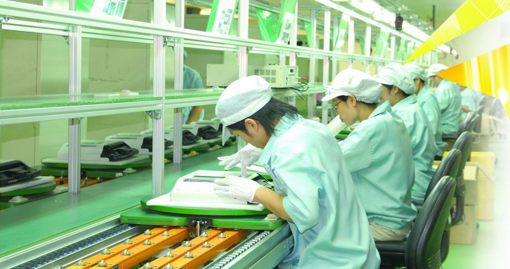
Product Assembly and Quality Control
With the special Smart MES system developed by ourselves, which has a solid efficiency foundation of piece-rate system and is very flexible and efficient, saves around 30%+ lead-time than ordinary assembly lines, also saves assembly costs by 15%+ for customers, and at the same time, makes sure our operators get paid 20%+ higher than the normal salary in the neighborhood. You can learn more about our MES system through the link: www.xgmes.com.
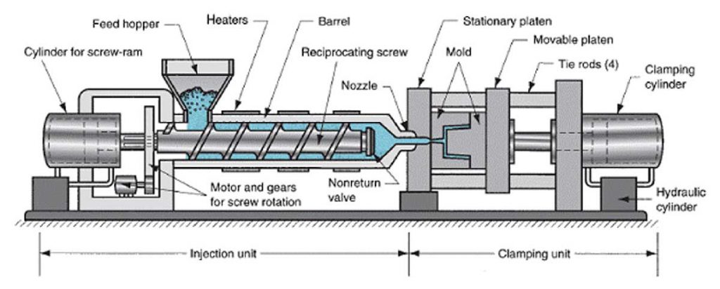
Plastic Injection Molding
Polymer granules are dried to exactly the right water content and fed into the hopper. Any pigments are added at this stage at between 0.5% and 5% dilution.
The material is fed into the barrel, where it is simultaneously heated, mixed and moved towards the mold by the rotating action of the Archimedean screw. The melted polymer is held in the barrel momentarily as the pressure builds up ready for injection into the mold cavity.
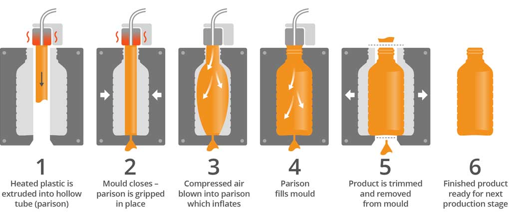
Plastic Blowing Molding
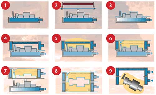
In stage 1 of the EBM process, a conventional extrusion assembly feeds plasticized polymer into the die. The polymer is forced over the mandrel and emerges as a circular tube, known as an extruded parison. The extrusion process is continuous. In stage 2, once the parison has reached a sufficient length the 2 sides of the mold close around It. A seal Is formed along the bottom edge. The parison Is cut at the top by a knife and moved sideways to the second station, where air is blown in through a blow pin, forcing the parison to take the shape of the mold. The hot polymer solidifies as It makes contact with the cold tool.
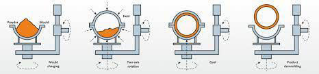
Plastic Rotatioinal Molding
The rotation molding process starts with the assembly of the metal molds on the rotating arm. A predetermined measure of polymer powder is dispensed evenly into each mold. It is closed, clamped and rotated into the heating chamber. There it is heated up to around 250°C(820 °F) for 25 minutes and is constantly rotated around its horizontal and vertical axes.
Plastic/Rubber Vacuum Molding
In stage 1, the two halves of the mold are brought together. Molds are typically made in two halves: parts A and B. Inserts, cores and additional mold parts can also be incorporated for complex parts.
The two separate parts of PUR are stored at 40°C (104°F). Mixing them together causes a catalytic and exothermic reaction to take place, and the PUR warms up to between 65°C and 70°C (149-158°F).
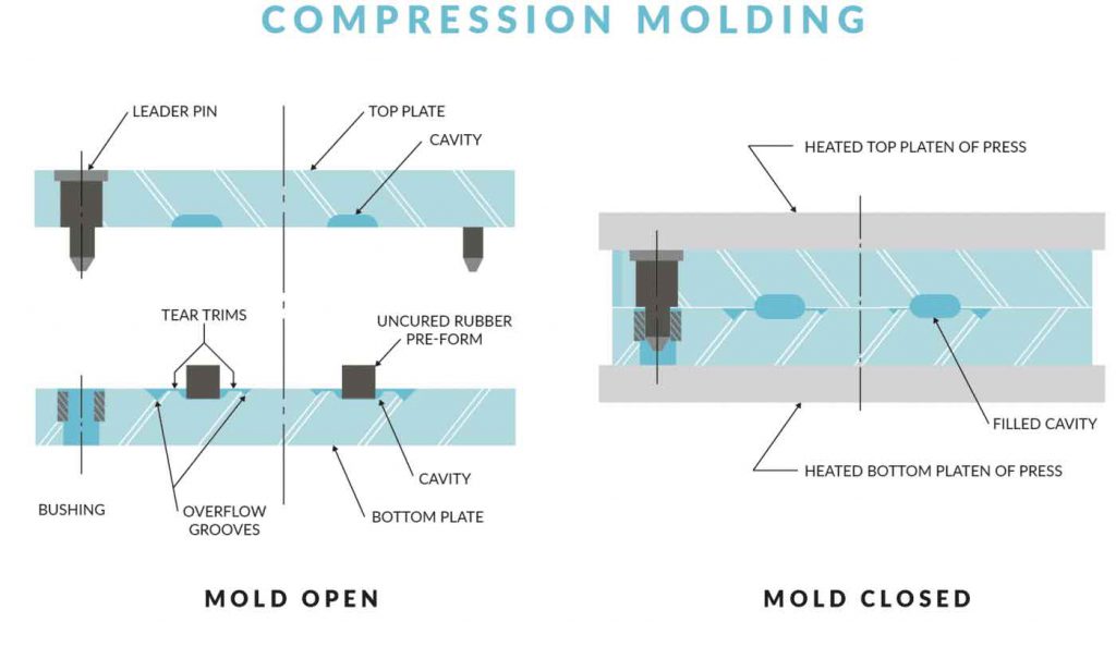
Rubber Compression Molding
The sequence for compression molding rubber is identical to compression molding plastic except that the cycle time is slightly longer. To show the different compression molding techniques, here a sheet geometry has been used instead of a side action tool.
In stage 1, the rubber is conditioned to remove any crystallinity that might have built up since its production. Then a measure of conditioned rubber is placed in the lower mold. In stage 2, the 2 halves of the mold are brought together and pressure is applied gradually to encourage the material to flow.
Sheet Metal Stamping
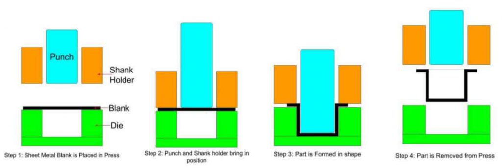
Metal stamping is carried out on a punch press. The power is transferred to the punch by either hydraulic rams or mechanical means such as a fly press. Hydraulic rams are generally preferred because they supply even pressure throughout the stamping cycle. Even so, fly presses still have their place in the metalworking industry.
The punch and die (matched tooling) are dedicated and generally carry out a single operation such as forming or punching. In operation, the metal blank is loaded onto the stripper. The punch then clamps and forms the part in a single stroke.
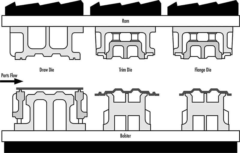
Sheet Metal Deep Drawing
The deep drawing process is carried out in different ways - the method of process being determined by the complexity of the shape, depth of draw, material and thickness. In stage 1, a sheet metal blank is loaded into the hydraulic press and clamped into the blank holder. In stage 2, as the blank holder progresses downwards the material flows over the sides of the lower die to form a symmetrical cup shape. In stage 3, the punch forces the material through the lower die in the opposite direction. The metal flows over the edge of the lower die to take the shape of the punch. In stage 4, the part is ejected.
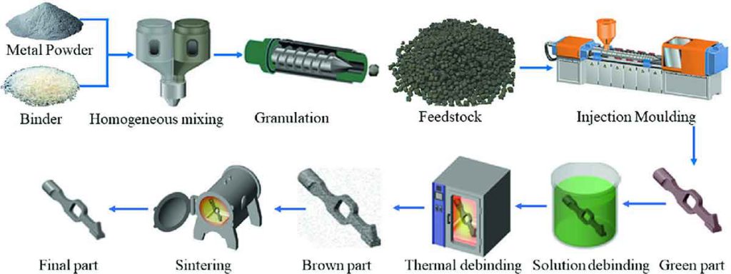
Metal Injection Molding
Fine metal powder, typically no larger than 25 microns (0.00098 in.) in diameter, is compounded with a thermoplastic and wax binder. The spherical metal particles make up roughly 80% of the mixture. The manufacturers themselves often make up this feedstock and so the exact ingredients are likely to be a well-guarded secret.
For MIM, the injection molding machines are modified slightly in order to accommodate the plasticized powder composite material.
In stage 1, the injection cycle is much the same as for other injection molding processes, although the molded parts are roughly 20% larger in every dimension prior to heating and sintering. This is to allow for the shrinkage, which will take place as the binder is removed.
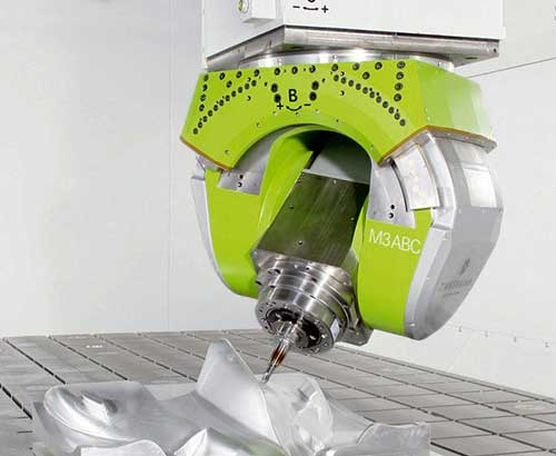
CNC(computer numerical control) Machining
CNC machining is a term commonly used in manufacturing and industrial applications. But exactly what is CNC? And what is a CNC machine?
CNC 101: The term CNC stands for 'computer numerical control', and the CNC machining definition is that it is a subtractive manufacturing process which typically employs computerized controls and machine tools to remove layers of material from a stock piece—known as the blank or workpiece—and produces a custom- designed part. This process is suitable for a wide range of materials, including metals, plastics, wood, glass, foam, and composites, and finds application in a variety of industries, such as large CNC machining, machining of parts and prototypes for telecommunications, and CNC machining aerospace parts, which require tighter tolerances than other industries. Note there is a difference between the CNC machining definition and the CNC machine definition- one is a process and the other is a machine.
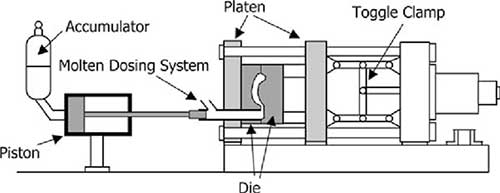
Metal Die Casting
High pressure die casting is carried out as a hot or cold chamber process. The only difference is that in the hot chamber method the molten metal is pumped directly from the furnace into the die cavity. The machine sizes range from 500 tonnes (551 US tons) to more than 3,000 tonnes (3,307 US tons). The required clamp force is determined by the size and complexity of the part being made.
Metal ingots and scrap are melted together in a furnace that runs 24 hours a day. In stage 1 of the cold chamber method, a crucible collects a measure of molten metal and deposits it into the shot cylinder.
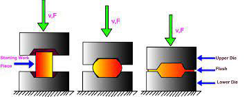
Metal Forging (Drop Forging)
The drop forging process is carried out using either a closed or open die. An open die Is typically used for drawing out (elongating a part and reducing its cross-section), upsetting (shortening a part and increasing its cross-section) and conditioning (preparing a part for closed die forging). Open die forging is also used to shape hexagonal and square section bars. The tool face is generally square or v-shaped for simple forming. The workpiece is repositioned between each drop of the hammer by the operator. This requires a great deal of operator skill and experience and is not suitable for automation. Long profiles can be forged in sections.
Closed die forging can be automated for high volume production.
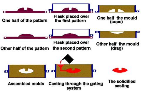
Metal Sand Casting
The sand casting process is made up of 2 main stages: mold-making and casting. In stage 1 the mold is made in 2 halves, known as the cope and drag. A metal casting box is placed over the wooden pattern and sand is poured in and compacted down.
For dry sand casting the sand has a vinyl ester polymer coating, which is cured at room temperature. The polymer coating on each sand particle helps to achieve a better finish on the cast part because it creates a film of polymer around the pattern, which forms the surface finish in the cast metal. For green sand casting, the sand Is mixed with clay and water until it is sufficiently wet to be rammed into the mold and over the pattern.
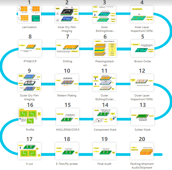
PCB (Printed Circuit Board) Manufacturing
A printed circuit board (PCB) mechanically supports and electrically connects electrical or electronic components using conductive tracks, pads and other features etched from one or more sheet layers of copper laminated onto and/or between sheet layers of a non-conductive substrate. Components are generally soldered onto the PCB to both electrically connect and mechanically fasten them to it. Printed circuit boards are used in all but the simplest electronic products. They are also used in some electrical products, such as passive switch boxes.
Alternatives to PCBs include wire wrap and point-to-point construction, both once popular but now rarely used. PCBs require additional design effort to lay out the circuit, but manufacturing and assembly can be automated. Electronic computer-aided design software is available to do much of the work of layout. Mass- producing circuits with PCBs is cheaper and faster than with other wiring methods, as components are mounted and wired in one operation.
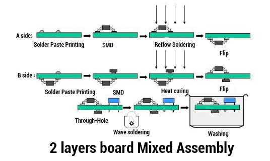
PCBA (Printed Circuit Board Assembly) Service
PCBA is one electronic part with assembled components (such as capacitance, resistance, IC, connector, etc.) on PCB, with SMT, DIP, and soldering assembly technology. All electronic devices have PCBA, and Electronic devices are everywhere. They range from smartphones to microwave oven and from laptops to cars. So almost everyone is familiar with them. This article explains PCBA manufacturing, PCB Services, PCBA China and much more.
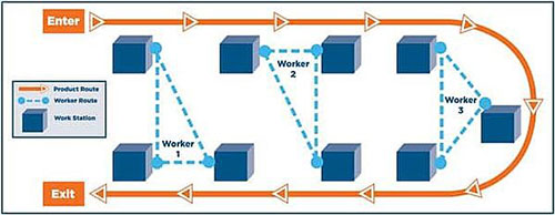
Final Product Assembly Service
The final assembly usually contains component assembly, test and packaging. A few fixtures and test equipment may get involved.
With professional engineers, skillful workers and strict quality control system, we are able to do the assembly with high efficiency and also high quality.