Master Design for Manufacturing (DFM) principles, checklists, and processes to reduce production costs, prevent tooling errors, and scale smoothly. Partner with Precintl for expert OEM / ODM product development today .
What Is Design for Manufacturing (DFM)?
Design for Manufacturing (DFM) is an engineering practice where parts and products are designed specifically to simplify the production process. Instead of creating a theoretical 3D CAD model and handing it off to a shop floor, DFM integrates manufacturing constraints directly into early engineering workflows. Doing this early prevents late-stage geometry changes, lowers unit costs, and eliminates tooling re-works.
Design for Manufacturing vs. Design for Manufacturability
Engineers often use these terms interchangeably, but they reflect slight differences in application:
- Design for Manufacturing: The active engineering methodology and set of design rules applied to lower production complexity, shrink cycle times, and minimize material waste.
- Design for Manufacturability: The overall rating or measure of how easily a given part geometry, PCB layout, or structural assembly can be produced using specific factory machinery and tooling.
What DFM Means in Modern Product Development
Modern hardware production relies on tight supply chains, rapid validation loops, and strict cost targets. In this context, DFM aligns industrial design with real-world factory capabilities. It bridges the gap between how a product looks on a computer screen and how it performs on a high-speed production line. DFM touches every physical aspect of hardware creation—from selecting the right aluminum alloy for CNC machining to setting exact wall thickness limits for an injection-molded enclosure.
Why Manufacturability Should Be Considered Early in Product Design
Fixing a design issue during the initial sketch phase costs practically nothing. Fixing that same issue after hard steel tooling is cut can cost tens of thousands of dollars and delay launch schedules by months. Early manufacturability reviews identify steep draft angles, impossible undercuts, or tight tolerances before capital is committed to tooling.
| Product Development Phase | Relative Cost Impact of Design Changes | Primary Focus & Action Items |
| Concept & Sketch | Extremely Low ($) | Evaluating product shape, basic dimensions, and feature feasibility |
| Detailed CAD Design | Low ($$) | Applying draft angles, wall thickness, fillets, and preliminary GD&T |
| Prototyping (EVT) | Moderate ($$$) | Validating functional fit, material properties, and early part geometry |
| Tooling & Validation (DVT/PVT) | High ($$$$) | Fixing mold defects, modifying steel tooling, adjusting tolerances |
| Mass Production | Severe ($$$$$) | Scrapping tooling, line shutdowns, product recalls, and high scrap rates |
What Is Design for Manufacturing and Assembly (DFMA)?
Design for Manufacturing and Assembly (DFMA) combines two distinct disciplines: optimizing individual components for fabrication (DFM) and optimizing how those components fit together on an assembly line (DFA).
DFM vs. DFA vs. DFMA
| Methodology | Primary Target | Main Focus | Typical Action Steps |
| DFM | Individual Parts | Raw material processing, mold flow, machining speed, tooling life | Adjusting draft angles, standardizing wall thickness, eliminating undercuts |
| DFA | Product Assembly | Assembly speed, line ergonomics, error-proofing, labor cost | Reducing total part count, replacing threaded fasteners with snap fits, adding self-aligning features |
| DFMA | Complete System | Whole-product unit economics, total bill of materials (BOM), system reliability | Consolidating multi-part bracket systems into single molded structural units |
How Manufacturing and Assembly Decisions Work Together
Part design directly impacts assembly workflows. For example, if a product design engineer reduces five separate sheet metal brackets into a single injection-molded structural rib, they complete two goals simultaneously: they simplify part production management (DFM) and eliminate four manual assembly steps on the factory line (DFA).
When DFMA Is More Appropriate Than DFM Alone
DFM alone works well for simple standalone hardware, custom machined blocks, or single-part enclosures. However, complex multi-component products—like consumer electronics, medical hardware, and connected IoT gateways—require a complete DFMA analysis. Ignoring assembly constraints while optimizing individual parts leads to line bottlenecks, misplaced wiring harnesses, and high labor overhead during mass production.
Why DFM Matters for Product Development
DFM serves as the foundation for transition from working prototype to scalable commercial product. Applying structured engineering rules prevents production surprises and keeps unit economics healthy.
Reducing Manufacturing and Tooling Costs
Tooling mistakes cost real money. When a plastic injection mold requires manual modification due to improper sink marks or severe shrinkage, steel must be re-cut or welded. Applying proper DFM principles—like maintaining uniform wall thickness and using appropriate fillet radius values—extends mold life, prevents costly mold modifications, and reduces raw material waste.
Improving Production Quality and Yield
Variability causes defects. If a design requires tight machining tolerances that push CNC milling centers to their absolute precision limit, scrap rates spike. DFM establishes realistic dimensional tolerances and geometric tolerances that high-volume machinery can repeat reliably across thousands of units, directly lifting production yield.
Shortening Production and Assembly Time
Complex part geometries demand long tool paths, frequent machine setups, and multi-axis indexing. Simplifying part geometry cuts CNC machining run times directly. On the assembly side, using standardized hardware and self-locating features reduces the time labor operators spend positioning and securing components.
Preparing Products for Scalable Manufacturing
A design that works for 10 hand-built functional prototypes often fails at 10,000 units per month. DFM establishes repeatable parameters that allow contract manufacturer partners to scale up operations across multiple shifts or facilities without quality drops.
Core Principles of Design for Manufacturing
Applying these core manufacturing design principles prevents quality issues and reduces tooling cost before physical production begins.
Simplify Product and Part Geometry
Excessive internal pockets, deep narrow channels, and complex surface contours increase machining times and complicate mold extraction. Keep geometries straightforward. Use flat planes, standard bends, and standard cutter diameters whenever possible.
Minimize Unnecessary Features and Complexity
Every aesthetic line, non-functional radius, or cosmetic chamfer adds cost. Ask whether a decorative cutout or complex stepped contour adds functional value for the end user. If it adds machining operations or custom tooling requirements without improving function, remove it.
Design Appropriate Wall Thickness and Structural Features
Wall thickness dictates thermal performance and material flow during processing:
- Injection Molding: Non-uniform walls cause uneven cooling, internal voids, and visible sink marks. Maintain uniform wall thickness across the entire housing. Use ribs and bosses to add structural rigidity rather than increasing wall thickness.
- CNC Machining: Exceptionally thin walls vibrate under cutter pressure, causing chatter marks and dimensional errors.
- Die Casting: Thin sections freeze early, preventing full metal fill inside the cavity.
| Wall Thickness Design Approach | Structural & Aesthetic Outcome | Production Impact |
| Non-Uniform Wall Thickness | High internal stress, severe sink marks, cosmetic voids | Long cooling cycles, high scrap rate, mold warping |
| Uniform Wall with Support Ribs | High structural rigidity, uniform cooling, flat surfaces | Fast cycle times, low material usage, consistent yield |
Apply Practical Tolerances and GD&T
Over-specifying tolerances is one of the quickest ways to inflate product cost. Machining a feature to ±0.005 mm costs significantly more than holding a ±0.05 mm tolerance. Use Geometric Dimensioning and Tolerancing (GD&T) to define critical functional fit zones, and leave non-critical dimensions with standard commercial tolerances.
Select Materials Based on Manufacturing Requirements
Material selection shapes tool wear, cycle speed, and total cost. Machining high-grade titanium takes far longer than cutting standard 6061-T6 aluminum. Injection molding high-shrinkage crystalline resins requires tighter thermal control than using ABS. Select materials that balance mechanical stress needs with processing ease.
Standardize Components and Hardware
Avoid specifying custom screw thread sizes, unique spring lengths, or proprietary washers. Using off-the-shelf standard fasteners and hardware cuts component lead times, simplifies supply chain sourcing, and allows automated assembly tools to run smoothly.
Minimize Secondary Manufacturing Operations
Secondary operations—such as manual deburring, post-machining heat treatment, paint prep, pad printing, and surface polishing—add labor costs and scrap risk. Design features that exit primary tooling ready for use, or combine surface finish steps into the main production cycle.
DFM Considerations for Different Manufacturing Processes
Every manufacturing process comes with specific physical constraints. Optimizing a part requires matching its geometry directly to the intended production method.
DFM for Injection Molding
Plastic injection molding relies on fluid polymer flow, pressure distribution, and thermal cooling dynamics:
- Draft Angle: Apply a minimum 1.0° to 2.0° draft angle to all vertical walls parallel to the mold opening direction to allow clean part ejection without drag marks.
- Wall Thickness: Keep structural walls between 1.5 mm and 3.0 mm depending on material selection. Maintain uniform wall thickness across the entire part.
- Ribs and Bosses: Design structural ribs at 50% to 60% of the adjacent wall thickness to prevent visible sink marks on cosmetic outer surfaces.
- Undercuts: Avoid side cutouts that require expensive side-action sliders or lifters in the mold design.
DFM for CNC Machining
Subtracive machining relies on rotating cutting tools removing material from a solid billet:
- Internal Corner Radius: Avoid sharp internal 90-degree corners. End mills are round, so always design internal corners with a fillet radius slightly larger than standard cutter radii to prevent tool chatter.
- Pocket Depth: Limit deep pockets to less than four times the cutter diameter to prevent tool deflection and breakage.
- Setup Reduction: Design features so parts can be completely machined from a single direction or two parallel sides, minimizing multi-axis re-fixturing setup time.
DFM for Sheet Metal Fabrication
Sheet metal relies on cutting, punching, and press brake bending:
- Bend Radii: Maintain a consistent inner bend radius equal to or greater than the sheet material thickness across all bends.
- Hole Location: Place holes and cutouts at a distance of at least two times the material thickness away from bend lines to avoid hole stretching and distortion.
- Relief Cuts: Add rectangular or round relief notches at bend intersections to prevent material tearing along corner seams.
DFM for Die Casting
Die casting pours molten metal like aluminum, zinc, or magnesium into hardened steel dies under high pressure:
- Thermal Balance: Design gradual transitions between thick and thin wall sections to maintain consistent heat distribution during cooling.
- Draft Angle: Include 1.5° to 3.0° draft angles depending on whether zinc or aluminum alloys are used.
- Ejector Pins: Reserve flat internal areas for ejector pin placement where pin marks won’t ruin cosmetic surfaces.
DFM for Stamping and Forging
Stamping uses high-speed presses for high-volume metal parts, while forging shapes hot metal under high pressure for structural strength:
- Stamping: Maintain feature spacing relative to material thickness to prevent die edge chipping.
- Forging: Incorporate wide draft angles (3° to 7°) and large fillet radius profiles to allow hot metal to flow smoothly into complex cavity features without cold shuts or material laps.
DFM for 3D Printing and Rapid Prototyping
Additive processes remove tooling limits but bring unique build constraints:
- Self-Supporting Angles: Keep unsupported overhang angles above 45 degrees relative to the build platform to reduce support structure removal steps.
- Escape Holes: Include drainage paths to clear unfused powder or liquid resin from internal hollow chambers.
- Anisotropic Orientation: Orient mechanical load features along the horizontal build plane rather than across printed layer boundaries.
DFM for PCB Design and Electronics Manufacturing
Printed Circuit Board (PCB manufacturing) and automated PCB assembly require strict layout rules:
- Component Clearance: Maintain proper spacing around Surface Mount Technology (SMT) pads to prevent solder bridging and allow manual rework tools space to operate.
- Fiducial Marks: Place copper fiducial marks on PCB corners to guide pick-and-place camera alignment systems.
- Thermal Relief Pads: Use thermal relief trace designs on ground plane connections so soldering irons don’t sink heat away too quickly during assembly.
How the DFM Review Process Works
A structured DFM review brings product design engineers and contract manufacturer team members together to analyze parts line-by-line before cutting metal tooling.
| Review Step | Phase Title | Key Engineering Activities |
| Step 1 | Requirements Review | Evaluate mechanical load targets, environmental exposure, cosmetic standards, and target unit costs. |
| Step 2 | CAD & BOM Analysis | Inspect native 3D CAD models, 2D drawings, and BOM for missing draft, tight tolerances, and deep pockets. |
| Step 3 | Material Evaluation | Verify whether chosen resins, metal alloys, or PCB substrates suit the selected manufacturing process. |
| Step 4 | Risk Identification | Map potential failure points including mold flow lines, sink marks, part warping, and tight clearances. |
| Step 5 | Engineering Feedback | Generate detailed reports proposing design adjustments, feature consolidation, and draft angle tweaks. |
| Step 6 | Pre-Tooling Validation | Update 3D CAD models to confirm functional goals before approving steel tooling release. |
DFM Checklist for Product Designers and Engineers
Use this concise reference guide during CAD layout reviews before approving designs for production tooling.
| DFM Category | Critical Inspection Points | Target Engineering Criteria |
|---|---|---|
| Geometry & Features | Maintain uniform walls; add 1°-2° draft for molding; avoid undercuts; use generous internal fillets | |
| Material & Components | Use off-the-shelf standard fasteners; confirm material availability; size parts to standard bar stock | |
| Tolerances & Finish | Reserve tight tolerances for functional mating surfaces; select standard surface finish options | |
| Tooling & Production | Align draw directions; reduce multi-axis machine setups; position ejector pin marks inside non-cosmetic areas | |
| Assembly & Service | Minimize part count; provide tool clearance for assembly; add self-aligning chamfers | |
| Quality & Testing | Provide flat datum features for CMM measurement; expose PCB test pads for automated testing |
Common DFM Problems That Cause Manufacturing Issues
Ignoring basic production rules early in the product engineering process creates preventable production delays and unexpected expenses downstream.
Overly Tight Tolerances
Specifying a ±0.01 mm tolerance on a non-critical cosmetic cover forces the machine operator to slow tool feed rates, increases tool wear, and triggers constant CMM inspection stops. Apply tight tolerances only where components interface directly with moving parts or high-precision mechanical fits.
Difficult-to-Manufacture Geometries
Deep narrow channels, sharp internal square corners, and tall unsupported plastic towers drag down manufacturing performance. These features cause tool chatter on CNC equipment, trapped air bubbles in injection molds, and unstable metal flow in die casting dies.
Incorrect Material Selection
Choosing high-performance specialty polymers or high-hardness steel alloys when standard commercial grades perform the job inflates unit costs. Specialty materials usually demand longer molding cycle times, special tooling inserts, and tighter process controls.
Excessive Part Count
A product built from 50 individual custom metal stampings requires 50 sets of production tooling, complex inventory tracking, and long manual assembly lines. Combining features into consolidated structural parts drops production overhead quickly.
Complex Tooling Requirements
Designing parts with internal cutouts or side-holes that run perpendicular to the main tool opening direction forces toolmakers to add complex side-action slides, hydraulic lifters, or collapsible cores. This inflates upfront tooling cost and increases tool maintenance frequency.
Designs That Require Too Many Secondary Operations
If an aluminum housing requires CNC milling, secondary deburring, manual bead blasting, clear anodizing, and post-tap thread cleaning, each step introduces extra labor costs and potential scrap points. Look for ways to eliminate or combine post-processing steps.
How DFM Reduces Product Manufacturing Cost
Designing for production optimization systematically attacks hidden manufacturing costs across every stage of the product launch life cycle.
Design Complexity and Unit Cost
Simple part geometries reduce machine runtime, extend cutting tool life, and shorten injection molding cooling cycles. Every second shaved off a machine processing cycle lowers per-unit labor and energy costs.
Tooling Complexity and Upfront Investment
Tooling costs depend directly on part shape complexity. Eliminating side-actions, deep ribs, and textured surfaces reduces the machine hours needed to produce steel molds, lowering capital expenditure requirements before launch.
Production Cycle Time and Labor
Optimized designs let automated machines load, run, and unload efficiently. On the assembly side, self-locating alignment pins and snap-fit joints reduce the time line operators spend assembling each unit.
Scrap, Rework and Production Yield
Designs built with wide, stable processing windows produce fewer defects. Maintaining consistent wall thickness and applying practical GD&T limits raises first-pass production yield, cutting scrap rates and rework costs.
Design Changes Before vs. After Tooling
Modifying a digital 3D CAD model during a preliminary DFM review takes a few hours of engineering time. Modifying hardened steel injection tooling after buildout costs thousands of dollars and delays market deployment by weeks.
DFM and Product Assembly Optimization
Assembly efficiency relies on optimizing how individual parts interact within the final product enclosure.
| Assembly Feature | Traditional Assembly Approach | DFA Optimized Design Approach |
| Fastening Method | Multiple threaded screws driven from various angles | Integrated snap-fit hooks with single-direction screw fixation |
| Part Positioning | Manual alignment requiring specialized hold fixtures | Self-aligning lead-in chamfers and asymmetry features |
| Component Count | Multi-piece bracket, spacer, and enclosure sub-assemblies | Single consolidated injection-molded housing structure |
| Assembly Motion | Multi-axis flipping and manual rotational positioning | Top-down single Z-axis linear insertion |
Reducing Part Count
The most effective way to reduce assembly cost is to eliminate unnecessary components. Ask three questions for every part in an assembly:
- Does the part move relative to all other parts during operation?
- Must the part be made from a different material for insulation or strength?
- Would combining this part with another prevent necessary maintenance access?
If the answer to all three questions is “no,” consolidate the components into a single molded or machined structure.
Designing for Efficient Assembly
Design parts so they assemble top-down in a single vertical z-axis direction. Gravity assists line operators when components drop into place naturally without requiring manual flip steps or multi-axis hold fixtures.
Improving Fastening and Joining Methods
Threaded screws take time to insert and torque correctly. Where appropriate, replace threaded hardware with molded snap-fits, press-fit alignment pins, or ultrasonic weld joints to speed up line assembly rates.
Designing for Automated or Semi-Automated Assembly
Automated pick-and-place equipment requires predictable handling surfaces. Incorporate clear flat grip faces, asymmetrical orientation features that prevent backward insertion, and chamfered lead-in edges that guide mating parts into place automatically.
Improving Inspection and Serviceability
Design enclosures with quick-access access panels or removable housing clips so field service technicians can inspect or swap wear parts without dismantling the entire internal mechanical sub-assembly.
When Should You Perform a DFM Review?
DFM During Concept and Industrial Design
Industrial designers establish physical product dimensions, ergonomic shapes, and outer cosmetic lines during initial concept creation. Bringing a manufacturing engineer into early aesthetic reviews ensures that key surface profiles can be molded or machined without compromising the original design intent.
DFM During Engineering Development
As 3D CAD models take shape, design engineers select materials, calculate structural ribs, and set initial feature locations. Running continuous DFM checks during detailed 3D CAD modeling ensures wall thickness consistency and prevents undercuts before mechanical design lockdown.
DFM Before Prototype Production
Before ordering rapid prototypes or functional evaluation units, perform a preliminary supplier DFM review. This ensures the prototype build reflects the exact manufacturing process intended for production, rather than relying on rapid prototyping shortcuts that mask real-world mold constraints.
DFM Before Tooling and Mass Production
The final DFM sign-off occurs right before releasing drawings for production tooling or steel mold cutting. This deep review validates draft angles, parting lines, gate positions, ejector pin locations, and tolerance stack-ups across every sub-assembly.
DFM Throughout EVT, DVT and PVT
Engineering validation testing progresses through three distinct manufacturing milestone phases. DFM ensures the design transitions smoothly across each stage.
| Hardware Milestone Phase | Validation Objective | Primary DFM Focus Areas |
| EVT (Engineering Validation Test) | Functional & Mechanical Proof | Validating part fit, initial material choice, and basic geometry |
| DVT (Design Validation Test) | Production Tooling & Quality Yield | Fine-tuning mold flow, resolving sink marks, and setting tolerances |
| PVT (Production Validation Test) | Mass Production Line Speed | Optimizing assembly fixtures, line speed, and SMT yield |
| Mass Production | High-Volume Commercial Output | Monitoring process repeatability, tool wear, and continuous yield |
DFM During EVT (Engineering Validation Test)
The EVT phase proves that the design functions mechanically and electronically according to target specifications. DFM focus at this stage center on validating functional part fit, preliminary material selection, and resolving major structural geometry flaws using functional prototype tooling or CNC components.
Manufacturing Design Changes During DVT (Design Validation Test)
DVT uses final production-intent tooling and manufacturing processes to prove the product can meet quality and cosmetic standards. DFM activities in DVT focus on refining mold flow parameters, fine-tuning dimensional tolerances, eliminating cosmetic sink marks, and optimizing thermal cooling cycles.
Production Readiness During PVT (Production Validation Test)
PVT tests mass production line speed and operational throughput at target volume levels. DFM during PVT shifts to optimizing assembly fixtures, eliminating operator assembly bottlenecks, refining PCB surface-mount yields, and verifying final production line repeatability.
Transitioning From Validation to Mass Production
Once PVT yield targets are met consistently, the production design locks completely. Full DFM integration ensures contract manufacturer facilities can transition into full mass production run rates without unexpected line stops or tooling failures.
DFM Examples: Turning Product Designs Into Manufacturable Products

Plastic Enclosure DFM Example
- Initial Design Issue: A smart home controller housing had uniform 4.0 mm solid walls, sharp 90-degree internal corners, zero wall draft angles, and deep internal undercuts for snap clips.
- DFM Modification: Reduced base wall thickness to a uniform 2.0 mm with internal structural support ribs; added 1.5° draft angles across all vertical surfaces; modified snap clips to use pass-through core cutouts in the mold cavity.
- Result: Prevented surface sink marks, reduced mold cooling cycle time by 40%, and eliminated the need for side-action slide mechanisms in the injection mold tooling.
CNC-Machined Metal Part DFM Example
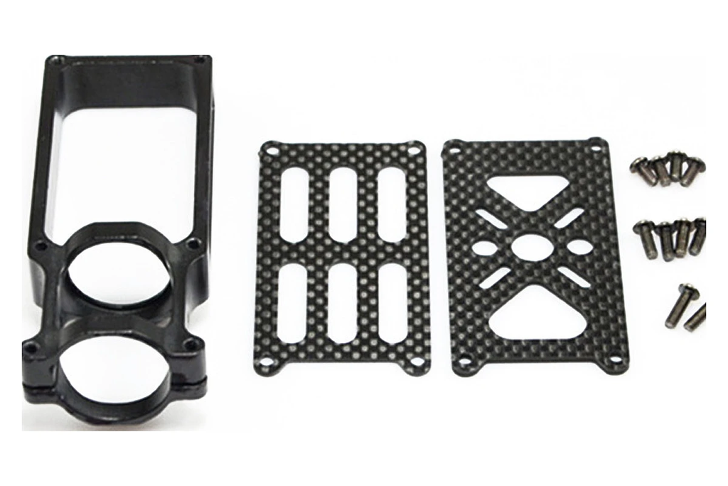
- Initial Design Issue: A drone motor mount plate featured sharp 90-degree internal corner pockets, a 50 mm deep narrow internal pocket, and specified a ±0.005 mm profile tolerance across non-mating outer surfaces.
- DFM Modification: Replaced sharp internal corners with a 3.5 mm fillet radius matching standard cutting tool sizes; reduced deep pocket depth to 20 mm; relaxed outer cosmetic tolerances to ±0.1 mm while retaining tight tolerance limits only on bearing mounting locations.
- Result: Reduced machine cutter cycle time from 45 minutes down to 12 minutes per part, extended end mill tool life, and cut unit production cost significantly.
Sheet Metal Product DFM Example
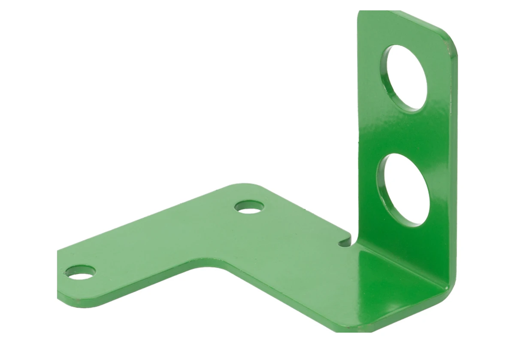
- Initial Design Issue: A server rack enclosure panel placed mounting screw holes immediately adjacent to sharp 90-degree press brake bend lines without relief slots.
- DFM Modification: Shifted hole center locations to a distance equal to three times the sheet thickness away from the bend line, and added tear relief cutouts at the corner seams.
- Result: Eliminated hole ovalization during bending and allowed high-speed automated punch presses to produce the panels cleanly.
Consumer Electronics DFM Example
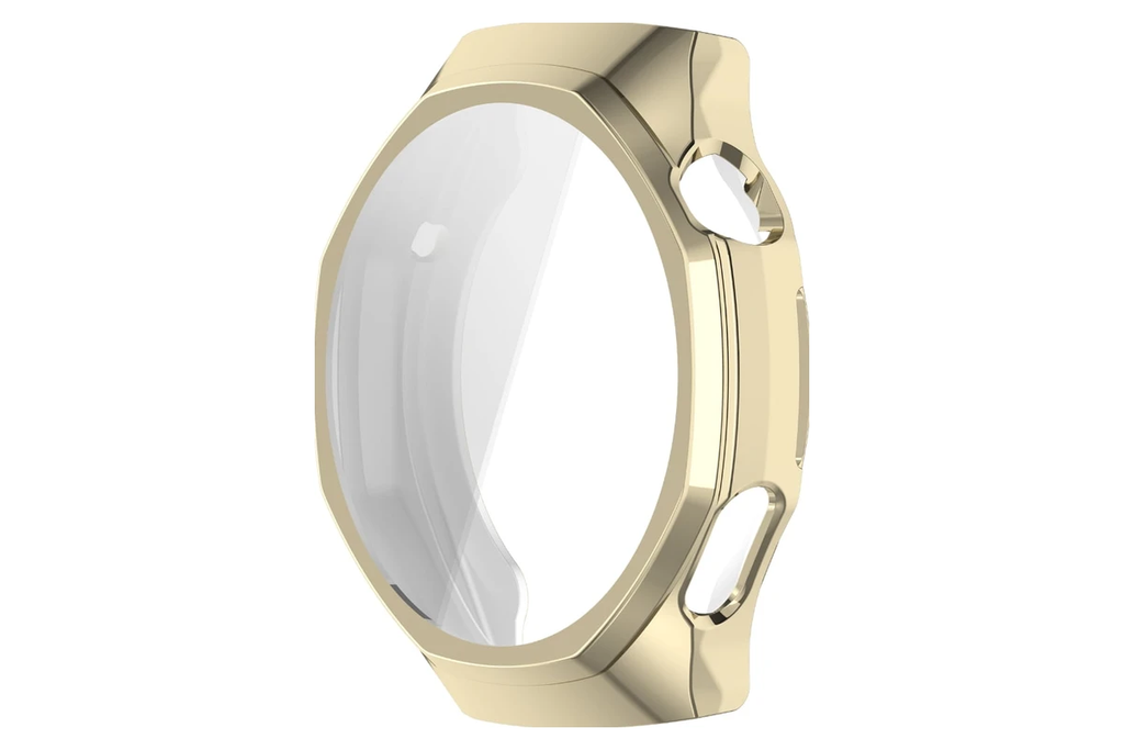
- Initial Design Issue: A wearable fitness device required 14 individual micro-fasteners driven from three different directions to seal the upper and lower housing sub-assemblies.
- DFM Modification: Redesigned the main enclosure to use internal snap-fit hooks along one edge combined with a perimeter ultrasonic weld seal, secured by two external screws on the bottom plate.
- Result: Cut mechanical assembly time by 65%, eliminated 12 micro-screws from the BOM, and improved the water resistance seal rating.
Connected IoT Product DFM Example
- Initial Design Issue: An industrial IoT gateway featured a multi-piece hand-soldered wire harness routing power between an internal sensor sub-board and the main system PCB.
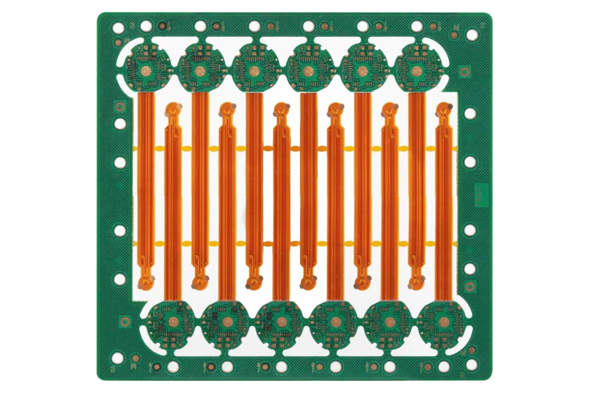
- DFM Modification: Replaced the separate sub-board and loose wire harness with a single rigid-flex PCB design that mated directly via automated surface-mount board-to-board connectors.
- Result: Streamlined internal wire routing, removed manual hand-soldering assembly steps, and prevented wire pinch defects during housing closure.
DFM for OEM and ODM Product Development
Working with established contract manufacturing partners allows brand owners to apply high-level manufacturing engineering expertise directly to custom hardware builds.
DFM for Custom OEM Products
In Original Equipment Manufacturing (OEM product development), the client owns the proprietary product design CAD files while the manufacturing partner builds the physical hardware. A robust OEM manufacturing workflow integrates supplier DFM review cycles early in the process to align client CAD models with the factory’s specific production capabilities.
DFM in ODM Product Development
In Original Design Manufacturing (ODM product development), the manufacturing partner provides pre-engineered base platform designs that brands can customize. ODM manufacturing leverages existing, pre-validated DFM designs and established tooling platforms to speed up time-to-market while reducing upfront development costs.
DFM for New Product Introduction (NPI)
Structured New Product Introduction programs rely on DFM milestones to de-risk production ramp-ups. Moving systematically through initial design review, EVT, DVT, and PVT phases keeps quality high while preventing costly engineering change orders (ECOs) during scale-up.
DFM From Prototype to Mass Production
A working 3D-printed functional prototype proves an idea works; engineering a manufacturable product design ensures it can be made profitably at scale. Early DFM execution bridges the gap between rapid prototyping and continuous high-volume factory production.
Related: OEM vs ODM Manufacturing: Which Is Right for Your Product?
DFM vs. Traditional Product Design
Traditional design workflows often operate in silos, while DFM integrates engineering and manufacturing decisions from day one.
| Engineering Approach | Workflow Model | Risk of Tooling & Cost Overruns | Primary Communication Channel |
| Traditional Product Design | Sequential (Siloed Hand-offs) | High (Defects discovered late in production) | Static drawing releases & ECO change orders |
| DFM Integrated Design | Concurrent (Cross-functional) | Minimal (Defects solved early in CAD stage) | Continuous DFM feedback & interactive reviews |
Design-Centered vs. Manufacturing-Centered Decisions
Traditional design approaches prioritize visual aesthetics and standalone functional performance, often treating factory tooling requirements as an afterthought. DFM balances cosmetic targets with practical tool building, material processing, and assembly constraints.
Product Performance vs. Manufacturability Trade-Offs
Pure mechanical design might call for a solid single-piece machined housing to reach maximum structural rigidity. Applying DFM engineering analysis evaluates whether a ribbed injection-molded housing or stamped metal frame delivers equal operational strength at a fraction of the unit cost and production time.
Balancing Cost, Quality, Function and Production Volume
Effective product design for manufacturing requires balancing four key engineering metrics:
- Function: Does the component satisfy performance and durability specs?
- Quality: Can the factory hold dimensional tolerances consistently?
- Production Volume: Is the selected manufacturing process optimized for the target run rate?
- Cost: Does the final unit cost fit the product’s market pricing model?
How to Choose a DFM Manufacturing Partner
Selecting the right contract manufacturer ensures your engineering team gets practical, actionable guidance that improves product performance and unit margins.
Engineering and DFM Expertise
Choose a contract manufacturer with experienced product development engineering teams across multiple disciplines, including plastic injection molding, CNC machining, sheet metal fabrication, and electronics assembly.
Manufacturing Process Capabilities
Look for manufacturing partners capable of supporting multiple production technologies in-house. A partner limited to CNC milling may bias design advice toward machining, whereas a multi-capable partner recommends the ideal process—whether die casting, stamping, or injection molding—for your target production volume.
Prototype and Tooling Capabilities
Evaluate whether the manufacturing partner manages precision tooling design and mold building directly. In-house mold building expertise ensures that supplier DFM review feedback accurately reflects practical steel tool construction constraints.
Quality Control and Testing Infrastructure
Ensure the contract manufacturer maintains rigorous quality control facilities, including CMM inspection equipment, environmental testing chambers, optical measurement systems, and ISO-certified quality control procedures.
Supply Chain and Component Management
A capable manufacturing partner manages raw material sourcing, standard component procurement, custom hardware inventory, and secondary finishing vendors, protecting your build against supply chain disruptions.
NPI and Mass Production Experience
Select a partner with a proven track record of guiding complex products through complete EVT, DVT, and PVT hardware validation phases into full mass production scale-up.
Why Choose Precintl for DFM, OEM and ODM Manufacturing?
At Precintl, we help global hardware innovators, brands, and industrial companies turn complex product concepts into scalable, production-ready hardware products.
Product Design and Engineering From Concept to Production
Our experienced product design engineers and manufacturing specialists support your project through every development phase. We work with your team to optimize CAD geometries, refine material choices, and establish efficient manufacturing workflows early.
DFM, Prototyping and Manufacturing Under One Partner
Precintl provides complete, end-to-end hardware development services under one roof. By combining upfront DFM engineering review, functional rapid prototyping, custom mold design, and high-volume mass production, we eliminate hand-off errors and shorten your total development schedule.
Manufacturing Support Across Multiple Production Technologies
Whether your product requires precision CNC machining, complex plastic injection molding, custom sheet metal fabrication, die casting, or electronic PCB assembly, our facilities deliver consistent production quality tailored to your exact production volume requirements.
EVT, DVT and PVT Product Validation
We guide your design through structured validation milestones. From early functional EVT prototypes through DVT tool tuning to final PVT mass production line validation, Precintl ensures your hardware meets strict performance, cosmetic, and yield targets.
OEM and ODM Manufacturing for Global Businesses
Precintl provides flexible OEM manufacturing and ODM product development solutions tailored to international brands. We protect your intellectual property, enforce strict ISO quality controls, and optimize unit economics to help you scale successfully in global markets.
Frequently Asked Questions About DFM and DFMA
What does DFM mean in manufacturing?
DFM stands for Design for Manufacturing. It is an engineering methodology focused on designing parts and hardware components to be easy, cost-effective, and efficient to manufacture using specific production processes like injection molding, CNC machining, or sheet metal fabrication.
What is the difference between DFM and DFMA?
DFM focuses on optimizing individual parts for efficient component fabrication. DFMA (Design for Manufacturing and Assembly) combines DFM with DFA (Design for Assembly), optimizing both individual part fabrication and the total system assembly workflow to reduce part counts, lower labor costs, and streamline line assembly.
What are the main principles of DFM?
The core principles of DFM include simplifying part geometry, maintaining uniform wall thickness, adding appropriate draft angles, applying realistic tolerances and GD&T, selecting easy-to-process materials, standardizing hardware components, minimizing secondary operations, and reducing total part counts.
What is included in a DFM checklist?
A comprehensive DFM checklist covers geometry rules (wall thickness, draft, fillets), material selection, dimensional tolerances, surface finish specifications, tooling ejection parameters, part consolidation features, and quality inspection datum points.
When should a DFM review be performed?
A DFM review should begin during early CAD modeling and engineering development, well before cutting production tooling. Iterative DFM reviews should occur before rapid prototyping, before ordering steel tooling, and throughout EVT, DVT, and PVT validation milestones.
How does DFM reduce manufacturing costs?
DFM cuts unit costs by shortening machine run times, reducing raw material waste, simplifying mold tooling designs, extending tool life, lowering assembly labor hours, and raising first-pass production yield to reduce costly scrap and rework.
What products can benefit from DFM?
Virtually any manufactured physical product benefits from DFM, including consumer electronics, automotive components, medical devices, connected IoT gateways, industrial machinery, plastic enclosures, structural sheet metal housings, and machined metal hardware.
Can DFM be used for electronics products?
Yes. In electronics, DFM includes PCB manufacturing and assembly optimization (often called DFM/DFA for SMT). It covers trace spacing, thermal relief pad designs, component clearances, fiducial mark placement, and housing assembly constraints.
What is a DFM analysis?
A DFM analysis is a formal engineering review conducted by manufacturing engineers or contract manufacturing partners. It evaluates a 3D CAD model against specific manufacturing process constraints, identifying potential defect risks and recommending geometric adjustments before tooling buildout.
Do OEM manufacturers provide DFM services?
Yes, leading OEM contract manufacturers like Precintl offer comprehensive DFM engineering reviews as part of their NPI and product development services, helping clients optimize custom designs before starting mass production tooling.
What is the difference between DFM and DFA?
DFM (Design for Manufacturing) targets the efficient fabrication of individual standalone components. DFA (Design for Assembly) targets reducing total part count, simplifying line insertion steps, and speeding up manual or automated product assembly.
Can DFM be performed before prototyping?
Yes, running a DFM review before prototype production ensures functional prototype units closely match the physical geometry, wall limits, and material characteristics of final mass-produced parts, leading to more accurate engineering validation test results.