Metal Injection Molding
TECHNICAL DESCRIPTION
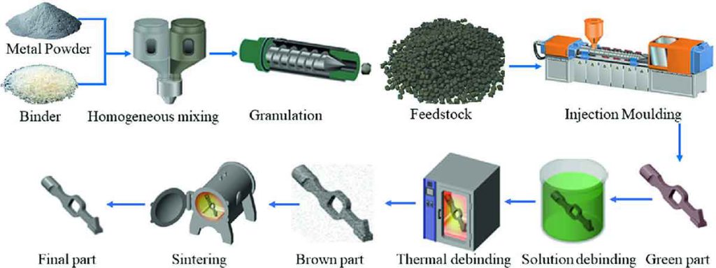
Fine metal powder, typically no larger than 25 microns (0.00098 in.) in diameter, is compounded with a thermoplastic and wax binder. The spherical metal particles make up roughly 80% of the mixture. The manufacturers themselves often make up this feedstock and so the exact ingredients are likely to be a well-guarded secret.
For MIM, the injection molding machines are modified slightly in order to accommodate the plasticized powder composite material.
In stage 1, the injection cycle is much the same as for other injection molding processes, although the molded parts are roughly 20% larger in every dimension prior to heating and sintering. This is to allow for the shrinkage, which will take place as the binder is removed.
In stage 2, the 'green' parts are heated in a special debind oven, to vaporize and remove the thermoplastic and wax binder. The molded parts are now in pure metal, with all binder material removed. The final stage is to sinter the parts in a vacuum furnace. This typically starts with a nitrogen/hydrogen mixture, (depending on material type) changing to a vacuum as the sintering temperature Increases. The 'green' part will shrink roughly 15-20% during sintering, to accommodate the loss of material during debinding. The resulting metal part has very little porosity. Certain parts, especially those with overhanging features, are supported in specially designed ceramic support plates so that they do not sag at high temperature. Parts with flat bases usually do not require additional support.
INTRODUCTION
Metal injection molding (MIM) is a powder process. A similar technique, known as powder injection molding (PIM), known as powder injection molding (PIM), is used to shape ceramic materials and metal composites.
MIM combines the processing advantages of injection molding with the physical characteristics of metals. It is thereby possible to form complex shapes, with intricate surface details and precise dimensions. Parts are ductile, resilient and strong, and can be processed in the same way as other metal parts, including welding, machining, bending, polishing and electroplating.
This process is suitable for forming small components generally up to 100 g (3-53 oz). As with conventional injection molding, MIM is predominantly used for high volume production, although low to medium volumes can be viable where MIM offers technical, design or production advantages over other manufacturing processes.
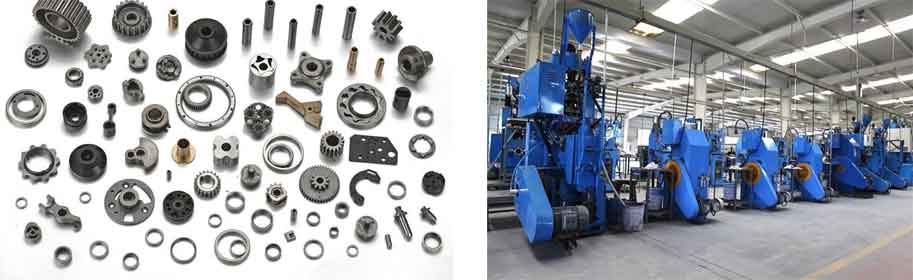
TYPICAL APPLICATIONS
MIM is capable of producing a wide range of geometries and so is utilized in many industries. The accuracy and speed of the process mate it ideal for manufacturing components for the aerospace, automotive and consumer electronics industries.
QUALITY
Like injection molding, the high pressures used in this process ensure good surface finish, fine reproduction of detail and, most importantly, excellent repeatability. However, MIM has the same potential defects, including sink marks, weld lines and flash. Unlike many plastics, metal parts can be ground and polished to improve surface finish.
Careful design will eliminate the need for secondary operations. This is especially important for flash at joint lines, which becomes a metal burr after sintering. This is normally readily removed after molding, but may be problematic in surface textures and threads. Both incorporating flat areas in threads and locating the partition line in non-critical areas reduce such problems.
After sintering, MIM parts are almost 100% dense and have isotropic characteristics. In other words, there is very little porosity. This ensures the structural integrity and ductility of the metal part.
DESIGN OPPORTUNITIES
Design opportunities and consideration for MIM are more closely related to injection molding than to conventional metalwork. For example, MIM can reduce the number of components and subsequent secondary operations of conventional metalworking because it can produce complex and intricate geometries in a single operation. For example, tools can have moving cores and unscrewing threads for example, making the inclusion of internal threads, undercuts, and blind holes possible.
Complex tooling, because it comprises moving parts, may increase tool costs significantly, but if it eliminates secondary operations on the MIM parts the extra costs can be offset, particularly where large volumes are required.
Without any additional costs textures and other surface details can be incorporated into the molding process, eliminating these as finishing operations. Holes and recesses can be molded into the metal part and it is feasible to produce these with a depth to diameter ratio of up to 10 to 1.
COMPATIBLE MATERIALS
The most common metallic materials for MIM are ferrous metals including low alloy steels, tool steels, stainless steels, magnetic alloys and bronze. Aluminum and zinc are not suitable, and parts in these materials can usually be made as die castings.
COSTS
Tooling costs are similar to plastic injection mold tools. The MIM materials are typically high cost, due to the level of processing and pretreatment necessary to make them suitable for the Injection molding operation. Injection cycle time is rapid: like plastic injection, the part is molded in 30-60 seconds. Unlike injection molding, the parts need to have the binder removed and then be sintered, which is usually done over a further 2-3 days, as the debinding time is 15-20 hours, plus several hours for sintering. Labor costs are low for injection molding because it is often fully automated. However, MIM requires sintering, which does increase manual operations and so costs.